Winder Mandrels
The Unique Design of Reverse Pyramid Winder Mandrel
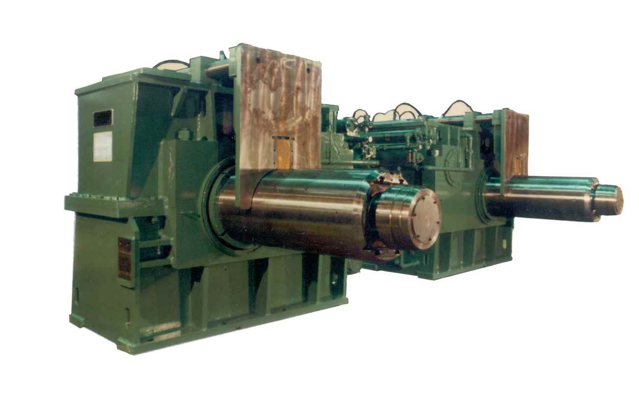
The Reverse Pyramid winder mandrel is a unique design developed by T. Sendzimir Inc., and it has been extremely successful in the rolling mill industry since its introduction in the years since.
What Sets Winder Mandrels Apart From The Rest
Sendzimir’s reverse pyramid winder mandrels are designed and built for up to 132,000 lbs. maximum tension. We have developed over 120 pairs of controlled collapse winder mandrels. The Sendzimir winder mandrel design evolved through 3 successive stages:
We first used the Forced Collapse design, then the Original Controlled Collapse Design Mandrel, and finally, we landed on our final stage: the Reverse Pyramid Mandrel. The orientation of the pyramids was reversed to enable a vastly superior mandrel design and reduced maintenance due to stronger construction, which is why it is the design Sendzimir still uses.
Standard Winder Mandrel Features
- Outboard Bearing Gates
- Easily Adjusted Gate alignment
- Quick Removal
- Integral Splines on the ID
- No coil breaks at segment corners, minimal at gripper slot
- Optimized Heat Treatment
- Shear Rings
- Mounted Screws
Although all the above features increase the initial cost of our winder mandrels, they ultimately result in safer operation, greater ruggedness, easier maintenance, and lower overall service costs.
Typical Mandrel Description & Scope of Supply
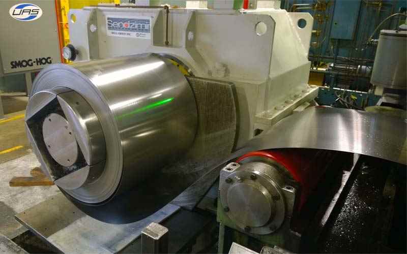
Reverse Pyramid winder mandrels are designed for 20” (508 mm), 24” (610 mm), and 30” (762 mm) diameters.
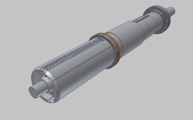
These mandrels are typically designed for under-winding. Each assembly consists of a mandrel, low-speed gear shaft, rotating cylinder, outboard gearing gate, and upward bearing gate with sliding sleeve.
Expand-Collapse of a winder mandrel works due to a rotating hydraulic cylinder that is mounted on the back end of the output shaft. It can be removed without disturbing the shaft or segments. The connection of the pyramid shaft to the rotating cylinder is provided by a threaded nut with integral shear ring.
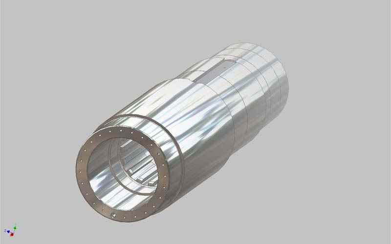
Collapsible Winder Mandrel Assembly consists of four segments mounted on a four step reverse pyramid shaft. Segments are designed to minimize coil breaks at the segment joints.
Pyramids and Segments are fabricated or forged, heat-treated, alloy steel with AMPCO bronze overlay weld deposited on the pyramid shaft surfaces.
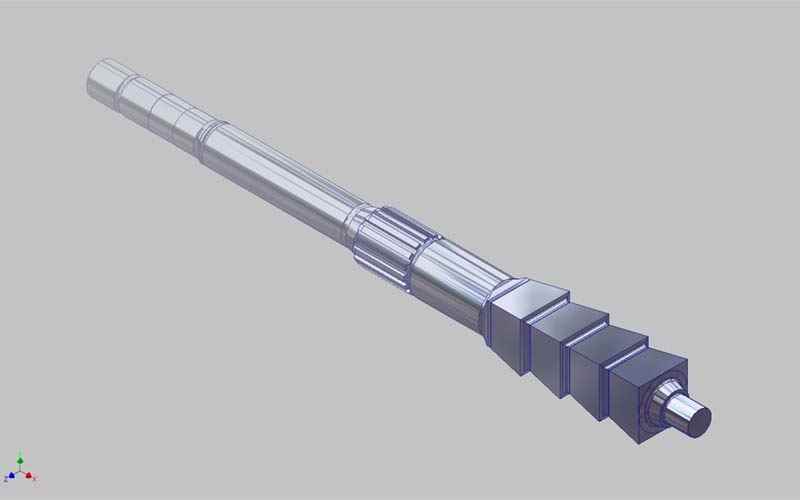
Pyramid Shaft, mounted on sleeve bearings in the gearbox output shaft, is an integral forged steel heat-treated unit. Our design ensures that there is no lateral movement of the segments during expand and collapse. This mandrel is designed for controlled collapse when subjected to hoop stress loading as the coil is wound onto the mandrel.
Gripper is hydraulically operated, and its profile is designed to minimize coil breaks.
Outboard Bearing Gate is designed to be easily aligned to the mandrel centerline by wedge adjustment in two planes.
Outboard Bearing is supported by a cylindrical sleeve within the outboard bearing gate which allows the mandrel shaft to move axially while still ensuring that the outboard bearing gate remains fixed. The sleeve will not engage with the outboard bearing on the mandrel unless the gate is properly aligned.
Experience the superior performance and reliability of Sendzimir's Reverse Pyramid Winder Mandrels.
Please fill out the form below. A member of our team will contact you shortly.